Here are the relations for representing spatial information for this iteration.
object has region region in camera's image
where region looks like:
[ {x:100,y:120}, {x:150,y:115}, {x:160,y:200}, {x:105,y:210} ]
This is used to specify the 2D contour in pixel space of a recognized framecode.
object has shape shape
where shape looks like:
{ shape: "rectangle", width: 8.5, height: 11 }
There will eventually be other shapes but for now we just have rectangles. Width and height (and all physical dimensions) are specified in inches.
If an object has a region and a shape (and you have the camera's intrinsic parameters), you can then derive the physical location of the object, relative to the camera:
object is located at location in camera's frame
where location looks like:
{ x: 4, y: 9, z: 82, rx: 0, ry: 0, rz: 1, theta: 0.05 }
The location specifies the position and orientation of the object, relative to another object's coordinate frame. x, y, and z specify the position (in inches). The orientation is specified as an axis vector (rx, ry, rz) and an angle in radians (theta) to rotate around that axis. (TODO: confirm with Luke, right-handed or left-handed rotation). The orientation spec is provisional -- we talked about using geometric algebra rotors -- but this is what Luke already has implemented for the illuminator and it's good enough to get started.
Notice that a location sample establishes a coordinate frame for the object, and that this coordinate frame is specified as relative to another object's coordinate frame. Every coordinate frame is always world scale, 1 unit is always 1 inch.
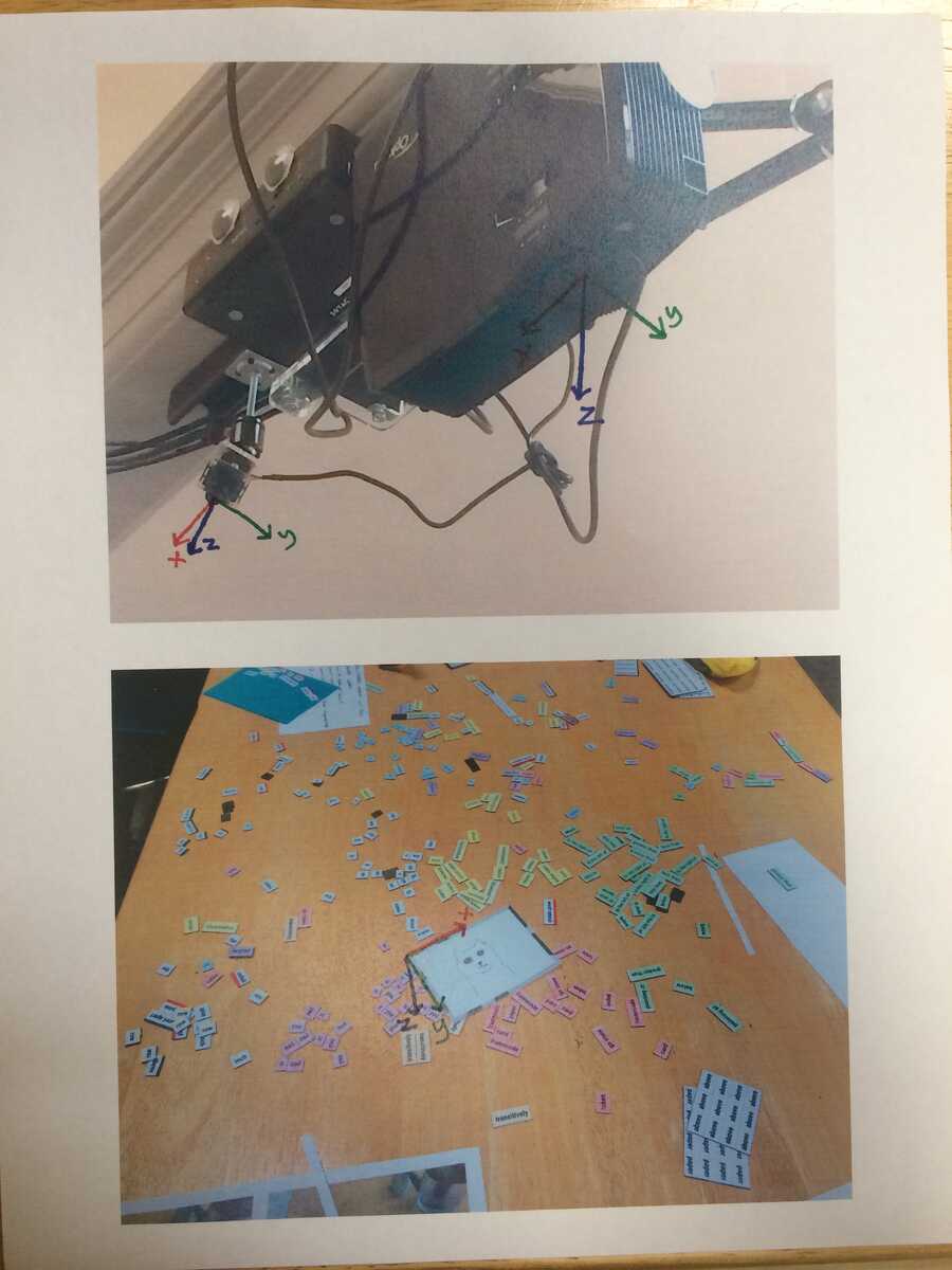
We'll use the convention that all coordinate frames are right handed. For cameras and projectors, the origin is the "eye" of the device. If you put your eye at the device's eye, x goes from left to right, y goes from top to bottom, positive z points straight ahead. For a framecode and other flat objects, the origin is at the top-left, so x goes left to right, y goes top to bottom, z goes into the table, away from you if you're looking at the object.
Here's where we are with calibration:
We're able to take an object of known size and its location in pixel space and produce the location sample. The next step is to calibrate the projector, which means we will have a sample saying the projector's location, relative to the camera. We'll also have the intrinsic parameters for the projector. With these we'll be able to do projection mapping.
Notice that every location is specified relative to another object. For framecodes, the recognizer always tags the location relative to the camera. To know where one objects is relative to an arbitrary other object (e.g. I want to know where a framecode is in a table's coordinate system), I see two ways we could implement this:
1. A library function where you give it the "home" object and the "target" object and it tells you the target object's location in the home object's frame. To do this, it looks at all the location samples and finds a path from one object to the other through this graph.
2. We have an object in the room that is the "global coordinate frame". This could be an actual object made out of 3 sticks pointing in x/y/z or something. Then we have a rule running that is always outputting location samples relative to this global frame. It does this by looking for objects that have known global location and traversing location samples to get the global location for other objects. This is similar to (1) but the library function above could be simpler: it would only have to look at the relation between the home and the global frame and the target and the global frame.