Hey All,
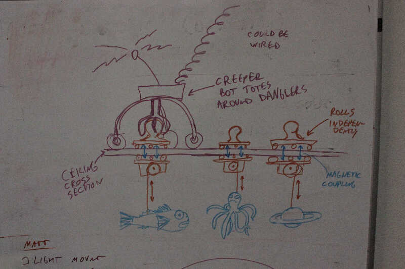
A meld between Joshua and Bret...
You could decouple the dangler from the movement above and use just a couple of bots that scoot around above the ceiling and magnetically couple to danglers below. everything couldn't move at once, but might be worth consideration.
Advantages:
- you can move to any position except those occupied by other danglers.
- you could move around alot of danglers using fewer robots and possibly tether the bots without them tangling up.
-no tracks or individual sections.
disadvantages:
-less weight capacity than direct coupling like in Joshua's design
-more complicated bot mechanics.
On Monday, August 1, 2016 3:46 PM, Joshua Horowitz <****************> wrote:
An all-powerful rigging system would allow us to move any object to any position and orientation in 3D space without human involvement. It would also allow the moved object to remain in place while other objects are moved about.
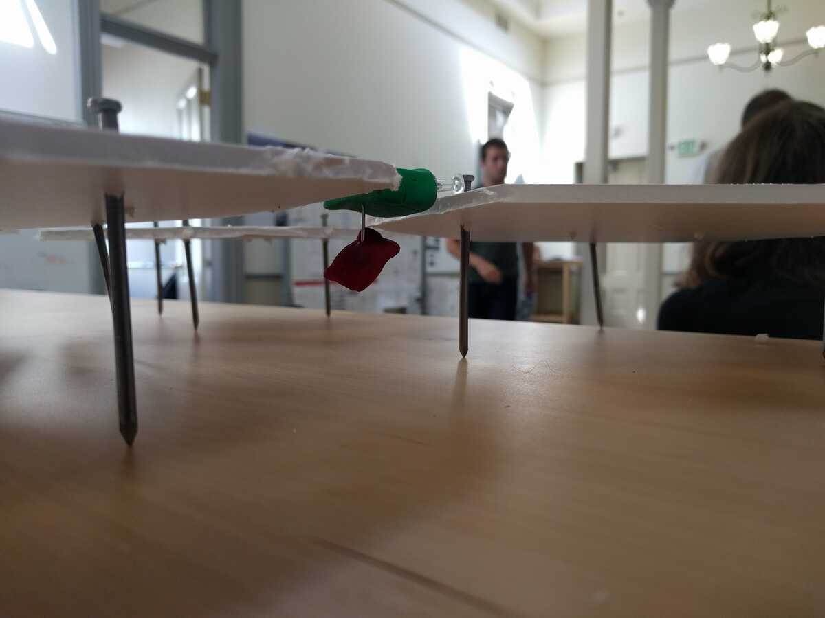
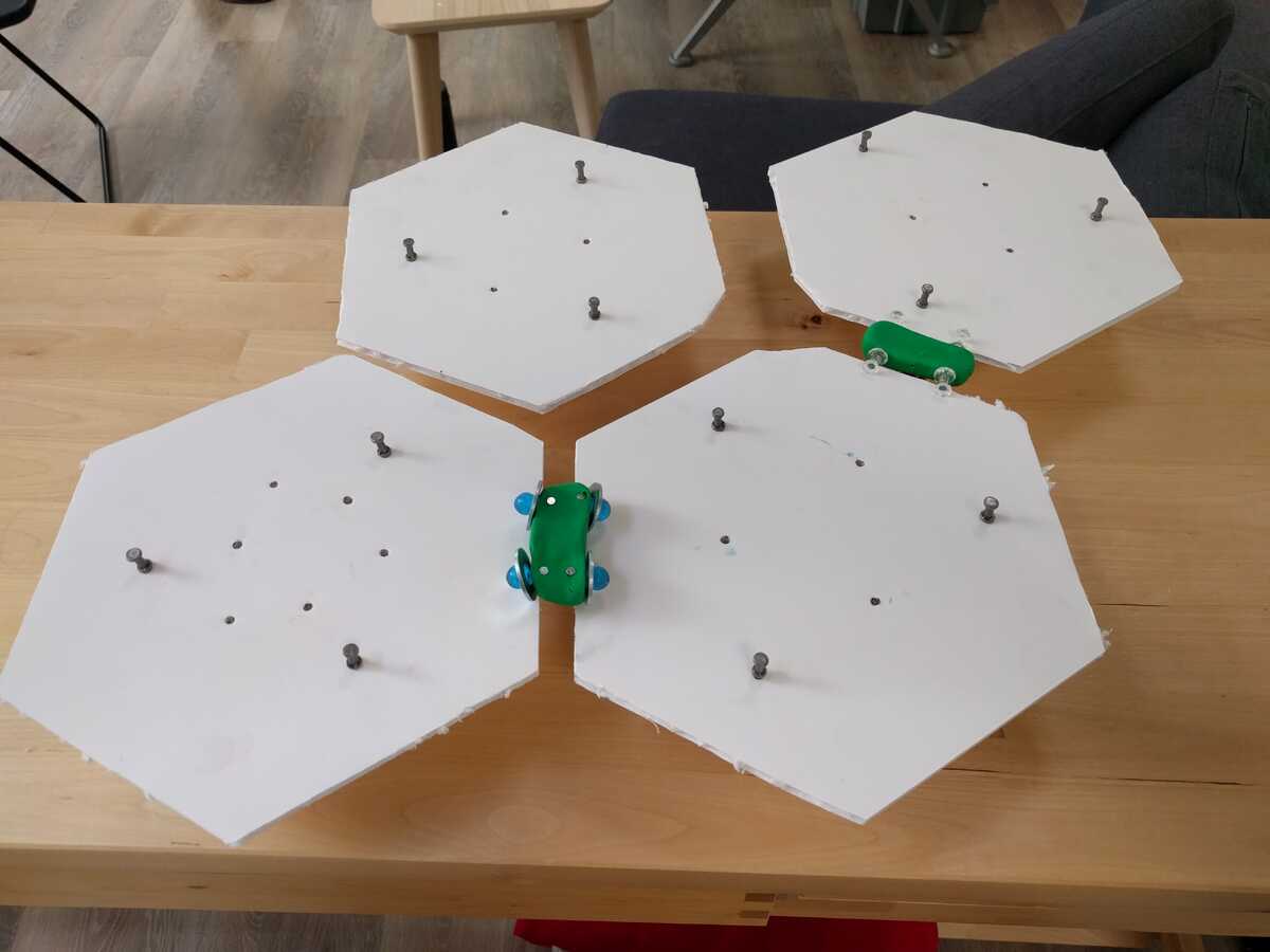
We've imagined a couple of "ceiling robot" systems which might be a way to pull this off. During the jam, I built a model of an idea I'd had in a previous discussion with Bret & Toby: plate-crawlin' ceiling robots!
The basic concept is that a bunch of solid plates (here, hexagons) are suspended from the ceiling, leaving slots between them. Robots can crawl around above the plates while objects are suspended on poles and cables beneath them.
So here's a red projector suspended beneath a green robot:
Building the model helped me think through some aspects of the design, both by myself and in conversation with the group.
When I put the first robot onto the model, its tiny push-pin wheels didn't give the robot enough clearance to stay out of the slots between plates. This fit the image of the system that I'd formed before: that robots would ride the "tracks" which formed along the edges of the slots. (This image is why I had picked hexagons for the plates – squares would demand sharp 90° turns, while hexagons only require 60° turns.)
But having the robot ride these tracks causes a pretty serious problem: We would really like the plates to be as small & densely-packed as possible, so that the robots can be positioned as accurately as possible. But if the robot is hanging out in the slots, then that puts a constraint on how small the plates can be, since the robots need to fit along the edges of the plates. In our jam discussion, someone asked what scale the model was built to. I realized that, for the robots to be a realistic size, the system would need to be several times larger than depicted, so the plates would have to be maybe 4-6 feet across. Depending on our desired usage, that might be ok, but at least at first glance, it is disappointingly far from our goal of moving an object to "any position".
Fortunately, the track-riding assumption is totally unnecessary. Big robots with big rubber wheels can just drive around however they want above the plates, as long as they keep their suspended poles/cables positioned above slots. The only limit to making plates as small as we want comes from the requirement that the plates be suspended from above – if each plate is attached to a steel rod at its center, then these rods will present a forest of obstacles for robots to navigate around. The horizontal gaps between adjacent rods will be about the size of the plates. That means the plates should be roughly 1-2 times the size of the robot. If the robot is 1 foot in horizontal size, the plates can be 1-2 feet in horizontal size, and that sounds pretty good to me. (Also, if you put a maneuverable drive system on the robots, you can make the plates square, which I think increases the density of slot positions.)
People asked about delivering power and ethernet to the robots. There are a few ideas for power. One is that power can be delivered by rails along the edges of plates. Another is that power outlets could be positioned at special stations along the grid, and robots could carry batteries to power movement between the stations. This second idea is based on the assumption that, while robots have fairly serious power requirements while they are in place, with computers and projectors and what-not running beneath them, they will have lighter-weight requirements while in motion (and motion won't last long anyway).
A similar pattern might apply to network connectivity. A robot in place, streaming video data from cameras or to projectors, will need a high-bandwidth connection. But a handful of robots moving from place to place might be able to get by with wifi. So maybe we can just have ethernet hook-ups positioned regularly along the grid of plates.
There are clearly a lot of details to work out here. But to me, the system now seems feasible.
On Mon, Aug 1, 2016 at 12:39 PM, Toby Schachman <****************> wrote:
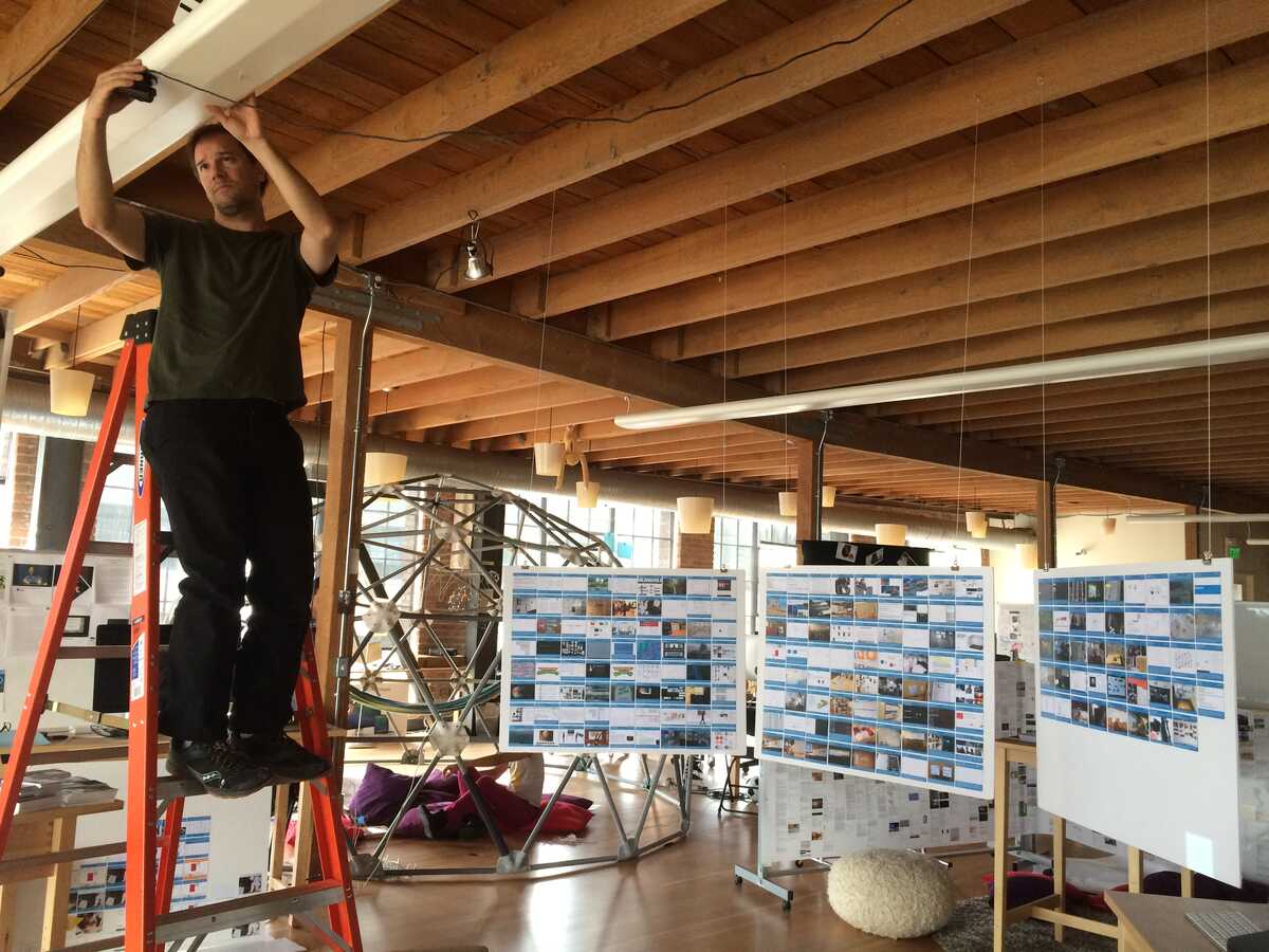
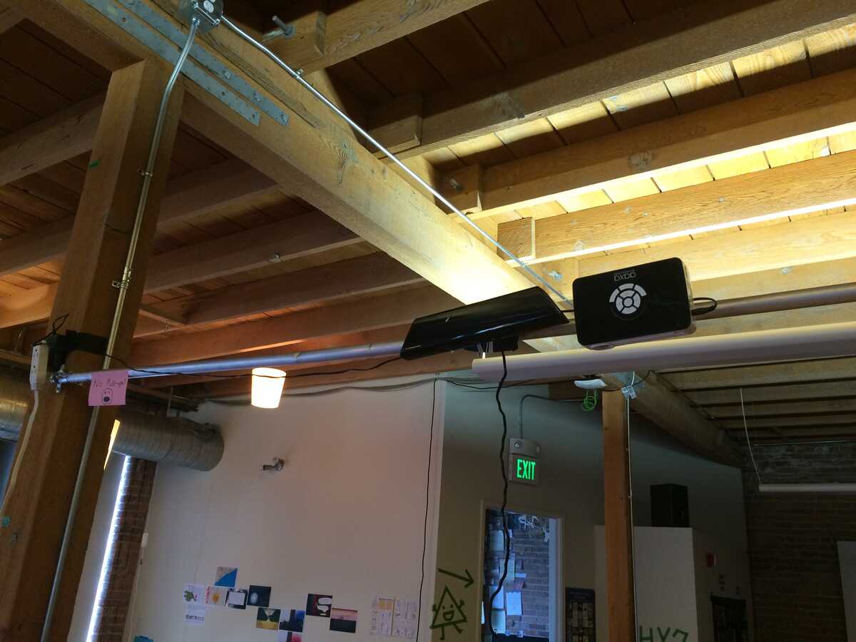
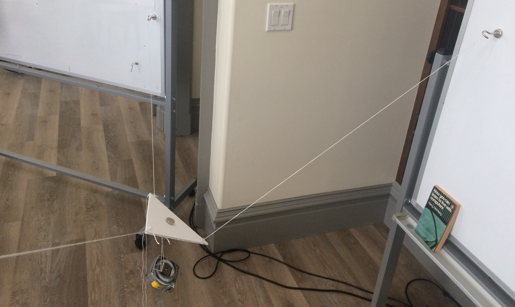
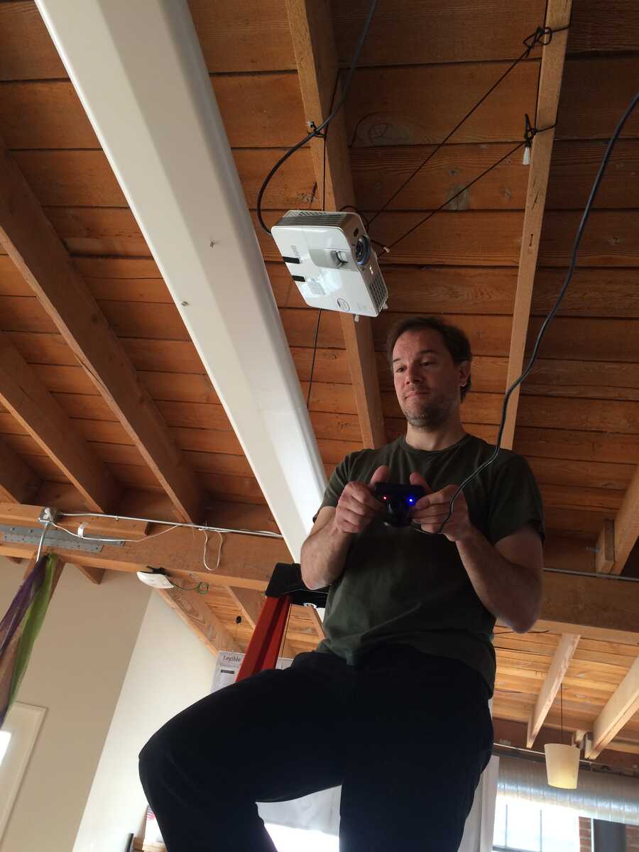
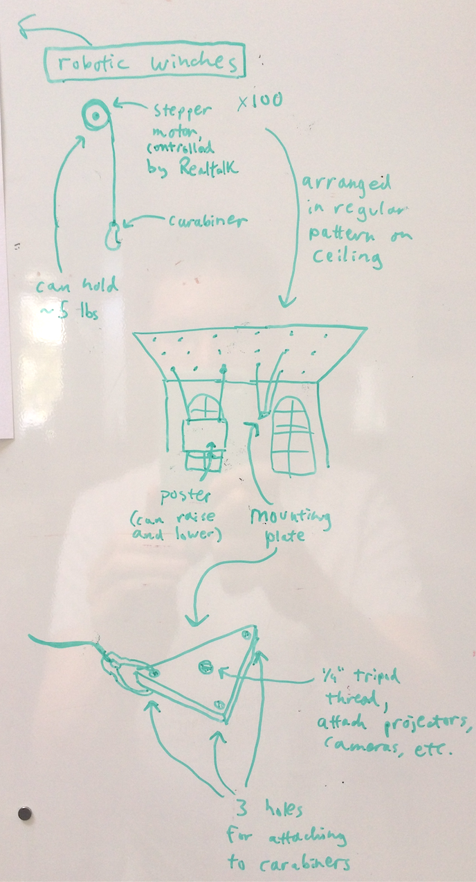
For my jam idea, I wanted to explore something that would be feasible and practical in the short term. One of the things we do a lot in the lab is mount projectors, cameras, and posters from the ceiling, off of columns, etc. Here are a few pictures from our old space:I would like to have a flexible way to suspend these things in space, in the position and orientation I want, without having to climb a ladder.So the idea is to have electronically controlled winches distributed over the ceiling.When you want to hang a thing, you laser point at 2-3 winches and they drop, you carabiner the cord to your object, then tell the winches to raise the appropriate distance. The winches are of course "objects" in Realtalk and can be controlled or programmed that way. (A use case for this is "storing" foamcore posters on the ceiling and lowering them when you need to refer to them.)One aspect I explored at the jam was whether having three strings would be sufficient to position and orient one of the triangular mounting plates. From this prototype, you can see that you can position the plate with the three strings, but you have less control over the orientation.With one additional string, I was able to achieve much more control over the orientation.I have since convinced myself that 5 strings is sufficient to achieve total control over position and orientation.Consider the case where you're hanging a foamcore poster using two winches.(a) If the poster is approximately centered between the two winches it will hang fine (as in the case with our old research gallery).(b) However, if you want the poster to be closer towards one side than the other, and adjust by pulling one of the strings shorter, the poster will tilt.(c) You can correct this by triangulating with a third string.You can make a similar argument for hanging the triangular mount. Use three strings from two winch points to fix one edge of the triangle between the two winch points. Now its only degree of freedom is radially around the axis formed by the two winch points. You can use two strings from a third winch point to remove this degree of freedom.It may not be necessary to have total control over the exact orientation of things we hang. We could just hang posters centered between two winch points like (a). And for cameras and projectors we could correct for minor orientation issues by cropping appropriately or using pan and tilt mirrors (which we might want on everything anyway).One way the winches might be implemented cheaply and effectively would be to use car window motors. These can be had for $10-15 each if we buy in bulk. They use worm gears, which don't back drive, so things won't fall if we lose power. They also seem about the right speed and load for what we're going for.Since these are DC motors, we could put an optical encoder on the pulley to get a feedback loop around how much we have reeled in the winch. We could also track the carabiners (string end points) with retroreflectors and get feedback this way.Our lab is ~4500 square feet. I did a cost estimate of what it would take to cover the ceiling with a regularly spaced grid of winches.Winch every __ ft # of winches Cost at $50 ea Cost at $100 ea1 4500 $225,000 $450,0002 1125 $56,250 $112,5003 500 $25,000 $50,0004 281 $14,050 $28,1005 180 $9,000 $18,000Some points that were made in the discussion:- Sway could be reduced by using the acceleration strategies that cranes use to not sway their loads.- The winches could be on sliding rails instead of a fixed grid. This would give us a bit more freedom about where they are on the ceiling. You'd move a winch (without a ladder) by telling it to come down, then pulling it by its end point (so each winch might also need a way to grab/let go of the rail). One thing this complicates is cabling to get power to the winches.
